Selasa, 19 Juni 2012

Control RGB LED with Arduino

control trials of pake Arduino RGB LED is connected to the computer via the SerialPort, making the GUI on a computer with VB.net (visual studio 2008).

Here is a screenshot of the experimental results and photos:


Program List for Arduino
/ / LEDRGB control program through the serial (RS232) 9600bps / / Microcontrollers: Arduino Duemilanove / / By: Aan Darmawan / / Date: December 26, 2010 / / How to control: information received from the serial code "000" s / d "999" / / Byte sequence control 1 red, 1 byte 1 byte green and blue / / 0 = means the darkest, 9 = mean terterang
/ / int ledrPin = 9; ledgPin int = 10; / / LED connected to digital pin PWM 9,10,11 ledbPin int = 11; faderValue int = 0; fadegValue int = 0; fadebValue int = 0;
void setup () {
   
Serial.begin (9600); / / enable 9600 bps serial communication
   
pinMode (ledrPin, OUTPUT); pinMode (ledgPin, OUTPUT);
   
pinMode (ledbPin, OUTPUT); } void loop () {
   
if (Serial.available ()> 0) / / read first byte of data as a red LED
   
{FaderValue = Serial.read ();
      
faderValue = (faderValue-47) * 10:34;}
   
if (Serial.available ()> 0) / / read second byte of data as a green LED
   
{FadegValue = Serial.read ();
      
fadegValue = (fadegValue-47) * 22:00;}
    
if (Serial.available ()> 0) / / read the third byte of data as a blue LED
    
{FadebValue = Serial.read ();
       
fadebValue = (fadebValue-47) * 25.50;}
   
/ / Send the PIN 9,10,11 (PWM)
   
analogWrite (ledrPin, faderValue);
   
analogWrite (ledgPin, fadegValue);
   
analogWrite (ledbPin, fadebValue);
 
delay (500); }


Programming in VB.net (visual studio 2008)

Programming:
 
Public Class Form1
     Dim red, green, blue As Integer
     Private Sub Button1_Click (ByVal sender As System.Object, ByVal e As System.EventArgs) Handles Button1.Click
         ColorDialog1.ShowDialog ()
         red = ColorDialog1.Color.R () \ 28.3333
         green = ColorDialog1.Color.G () \ 28.3333
         blue = ColorDialog1.Color.B () \ 28.3333
         TextBox1.Text = red & green & blue
         SerialPort1.Write (TextBox1.Text)
         BackColor = ColorDialog1.Color

     end Sub
     Private Sub Form1_Load (ByVal sender As System.Object, ByVal e As System.EventArgs) Handles MyBase.Load
         TextBox1.ReadOnly = True
SerialPort1.PortName = "COM2" 'Adjust to your computer
         SerialPort1.Open ()
         SerialPort1.Write ("000") 'RGB = 000 = black
     end Sub
end Class

Note:
In the Object Properties SerialPort1, do not forget the series adapted port name
(SerialPort1.PortName) to those available in the PC / Notebook you.

Congratulations to experiment .....


Rabu, 13 Juni 2012

Analog Read Voltage

This example shows you how to read an analog input on Pin 0, convert the values from analogRead() into voltage, and print it out to the serial monitor.

Hardware Required

  • Arduino Board
  • a variable resistor, like a potentiometer

Circuit

image developed using Fritzing. For more circuit examples, see the Fritzing project page
Connect the three wires from the potentiometer to your Arduino board. The first goes to ground from one of the outer pins of the potentiometer. The second goes from 5 volts to the other outer pin of the potentiometer. The third goes from analog input 2 to the middle pin of the potentiometer.
By turning the shaft of the potentiometer, you change the amount of resistance on either side of the wiper which is connected to the center pin of the potentiometer. This changes the voltage at the center pin. When the resistance between the center and the side connected to 5 volts is close to zero (and the resistance on the other side is close to 10 kilohms), the voltage at the center pin nears 5 volts. When the resistances are reversed, the voltage at the center pin nears 0 volts, or ground. This voltage is the analog voltage that you're reading as an input.
The Arduino has a circuit inside called an analog-to-digital converter that reads this changing voltage and converts it to a number between 0 and 1023. When the shaft is turned all the way in one direction, there are 0 volts going to the pin, and the input value is 0. When the shaft is turned all the way in the opposite direction, there are 5 volts going to the pin and the input value is 1023. In between, analogRead() returns a number between 0 and 1023 that is proportional to the amount of voltage being applied to the pin.

Schematic


Code

In the program below, the very first thing that you do will in the setup function is to begin serial communications, at 9600 bits of data per second, between your Arduino and your computer with the line:
Serial.begin(9600);
Next, in the main loop of your code, you need to establish a variable to store the resistance value (which will be between 0 and 1023, perfect for an int datatype) coming in from your potentiometer:
int sensorValue = analogRead(A0);
To change the values from 0-1023 to a range that corresponds to the voltage the pin is reading, you'll need to create another variable, a float, and do a little math. To scale the numbers between 0.0 and 5.0, divide 5.0 by 1023.0 and multiply that by sensorValue :
float voltage= sensorValue * (5.0 / 1023.0);
Finally, you need to print this information to your serial window as. You can do this with the command Serial.println() in your last line of code:
Serial.println(voltage)
Now, when you open your Serial Monitor in the Arduino development environment (by clicking the button directly to the right of the "Upload" button in the header of the program), you should see a steady stream of numbers ranging from 0.0 - 5.0. As you turn the pot, the values will change, corresponding to the voltage coming into pin A0.
/*
  ReadAnalogVoltage
  Reads an analog input on pin 0, converts it to voltage, and prints the result to the serial monitor.
  Attach the center pin of a potentiometer to pin A0, and the outside pins to +5V and ground.

 This example code is in the public domain.
 */


// the setup routine runs once when you press reset:
void setup() {
  // initialize serial communication at 9600 bits per second:
  Serial.begin(9600);
}

// the loop routine runs over and over again forever:
void loop() {
  // read the input on analog pin 0:
  int sensorValue = analogRead(A0);
  // Convert the analog reading (which goes from 0 - 1023) to a voltage (0 - 5V):
  float voltage = sensorValue * (5.0 / 1023.0);
  // print out the value you read:
  Serial.println(voltage);
}


LED Bar Graph

The bar graph - a series of LEDs in a line, such as you see on an audio display - is a common hardware display for analog sensors. It's made up of a series of LEDs in a row, an analog input like a potentiometer, and a little code in between. You can buy multi-LED bar graph displays fairly cheaply, like this one. This tutorial demonstrates how to control a series of LEDs in a row, but can be applied to any series of digital outputs.
This tutorial borrows from the For Loop and Arrays tutorial as well as the Analog Input tutorial.
The sketch works like this: first you read the input. You map the input value to the output range, in this case ten LEDs. Then you set up a for loop to iterate over the outputs. If the output's number in the series is lower than the mapped input range, you turn it on. If not, you turn it off. 

Hardware Required

  • Arduino Board
  • (1) LED bar graph display or 10 LEDs
  • (10) 220 ohm resistors
  • hook-up wire
  • breadboard

Circuit

 Schematic:


Code

/*
  LED bar graph

  Turns on a series of LEDs based on the value of an analog sensor.
  This is a simple way to make a bar graph display. Though this graph
  uses 10 LEDs, you can use any number by changing the LED count
  and the pins in the array.
 
  This method can be used to control any series of digital outputs that
  depends on an analog input.

  The circuit:
   * LEDs from pins 2 through 11 to ground

 created 4 Sep 2010
 by Tom Igoe

 This example code is in the public domain.

 http://www.arduino.cc/en/Tutorial/BarGraph
 */


// these constants won't change:
const int analogPin = A0;   // the pin that the potentiometer is attached to
const int ledCount = 10;    // the number of LEDs in the bar graph

int ledPins[] = {
  2, 3, 4, 5, 6, 7,8,9,10,11 };   // an array of pin numbers to which LEDs are attached


void setup() {
  // loop over the pin array and set them all to output:
  for (int thisLed = 0; thisLed < ledCount; thisLed++) {
    pinMode(ledPins[thisLed], OUTPUT);
  }
}

void loop() {
  // read the potentiometer:
  int sensorReading = analogRead(analogPin);
  // map the result to a range from 0 to the number of LEDs:
  int ledLevel = map(sensorReading, 0, 1023, 0, ledCount);

  // loop over the LED array:
  for (int thisLed = 0; thisLed < ledCount; thisLed++) {
    // if the array element's index is less than ledLevel,
    // turn the pin for this element on:
    if (thisLed < ledLevel) {
      digitalWrite(ledPins[thisLed], HIGH);
    }
    // turn off all pins higher than the ledLevel:
    else {
      digitalWrite(ledPins[thisLed], LOW);
    }
  }
}

Selasa, 12 Juni 2012

DIGITAL INFRARED MOTION SENSOR(PIR)

What is a PIR sensor and usability?

The usefulness of this sensor allows you to detect gerakan.Mereka often refer to this as the PIR sensor, "Passive Infrared", "pyroelectric", or "IR" movement sensor. / (Digital infrared motion sensor)

PIR is basically made ​​of a pyroelectric sensor (which you can see above a round metal can with a square crystal in the middle), which can detect infrared radiation levels. Everything emits some low-level radiation, and panas.Jika more radiation is emitted. Sensor detector will see the size of the IR from the other, and the output will swing high or low

SPECIFICATION:

  •      Type: Digital
  •      :3-5V Supply Voltage
  •      Current: 50μA
  •      Working temperature: 0 -70
  •      Output level (HIGH): 4V
  •      Output level (LOW): 0.4V
  •      Detect angle: 110 Degree
  •      Detect distance: 7 meters
  •      Size: 28mm x 36mm
  •      Weight: 25g
PIR sensor reading

PIR sensor connects to the microcontroller is really simple. PIR acts as a digital output, so all you need to do is use a pin to flip high (detected) or low (undetectable).

Power PIR to 5V and ground is connected to ground. Then connect the output to a digital pin. In this example we will use the pin 2.

The code is very simple, and basically just keep track of whether the input to pin 2 high or low. So that it prints a message when the movement has been started and stopped.

/*
 * PIR sensor tester
 */
 
int ledPin = 13;                // choose the pin for the LED
int inputPin = 2;               // choose the input pin (for PIR sensor)
int pirState = LOW;             // we start, assuming no motion detected
int val = 0;                    // variable for reading the pin status
 
void setup() {
  pinMode(ledPin, OUTPUT);      // declare LED as output
  pinMode(inputPin, INPUT);     // declare sensor as input
 
  Serial.begin(9600);
}
 
void loop(){
  val = digitalRead(inputPin);  // read input value
  if (val == HIGH) {            // check if the input is HIGH
    digitalWrite(ledPin, HIGH);  // turn LED ON
    if (pirState == LOW) {
      // we have just turned on
      Serial.println("Motion detected!");
      // We only want to print on the output change, not state
      pirState = HIGH;
    }
  } else {
    digitalWrite(ledPin, LOW); // turn LED OFF
    if (pirState == HIGH){
      // we have just turned of
      Serial.println("Motion ended!");
      // We only want to print on the output change, not state
      pirState = LOW;
    }
  }
}


Senin, 11 Juni 2012

INTRODUCTION TO THE ARDUINO


Arduino is a single-board micro controller that is open-source, derived from the Wiring platform, designed to facilitate the use of electronics in various fields. Atmel AVR processor has hardware and software has its own programming language.

history

This project began in Ivrea, Italy in 2005. Now it has more than 120,000 units sold. Massimo Banzi and its founders are David Cuartielles.


program example :

#define LED_PIN 13
 
void setup () {
    pinMode (LED_PIN, OUTPUT);     // enable pin 13 for digital output
}
 
void loop () {
    digitalWrite (LED_PIN, HIGH);  // turn on the LED
    delay (1000);                  // wait one second (1000 milliseconds)
    digitalWrite (LED_PIN, LOW);   // turn off the LED
    delay (1000);                  // wait one second
}


 Arduino-compatible boards


Because the design of hardware and software are open-source Arduino, 
other manufacturers are free to imitate, for example:


  1.     Freeduino
  2.     Cosmo Black Star
  3.     Freeduino MaxSerial
  4.     Zigduino

PLAY WITH HUMIDITY & TEMPERATURE SENSOR DHT11


DHT11 is the sensor temperature and humidity, he has a digital output signal is calibrated with temperature and humidity sensors are complex. This technology ensures high reliability and excellent long-term stability. microcontroller connected to the high performance of 8 bits. This sensor includes a resistive element and the NTC temperature gauges. Have excellent quality, quick response, anti-interference ability and high cost performance advantages.

Each sensor has a calibration feature DHT11 very accurate calibration of the humidity chamber. Calibration coefficients stored in the OTP program memory, internal sensors detect the signal in the process, we should call it the calibration coefficients. System of single-wire serial interface to be integrated quickly and easily. Small size, low power, the signal transmission distance up to 20 meters, so that different applications and even the most demanding applications. This product is 4-pin single pin package line. Convenient connection, special packages can be supplied according to user requirements.

specification

Supply Voltage: 5 V

Temperature range :0-50 ° C ± 2 ° C error

Humidity :20-90% RH ± 5% RH error

Interface: Digital


To display the temperature in laptop screen

Program on Arduino


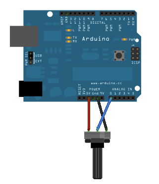
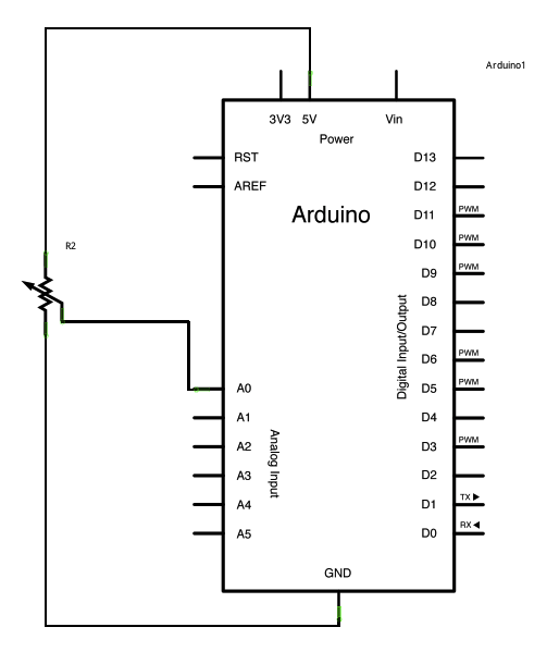
#define DHT11_PIN 0      // define analog  port 0
byte read_dht11_dat()
{
  byte i = 0;
  byte result=0;
  for(i=0; i< 8; i++)
  {
    while(!(PINC & _BV(DHT11_PIN)))
    {};  // wait  forever until anlog input port 0 is '1'   (NOTICE: PINC reads all the analog input ports
    //and  _BV(X) is the macro operation which pull up positon 'X'to '1' and the rest positions to '0'. it is equivalent to 1<
    delayMicroseconds(30);
    if(PINC & _BV(DHT11_PIN))  //if analog input port 0 is still '1' after 30 us
      result |=(1<<(7-i)); this="" position="" is="" 1="" p="">
    while((PINC & _BV(DHT11_PIN)));  // wait '1' finish
    }
    return result;
}
void setup()
{
  DDRC |= _BV(DHT11_PIN);   //let analog port 0 be output port
  PORTC |= _BV(DHT11_PIN);  //let the initial value of this port be '1'
  Serial.begin(9600);
  Serial.println("Ready");
}          
void loop() 
{
  byte dht11_dat[5];
  byte dht11_in;
  byte i;// start condition
  PORTC &= ~_BV(DHT11_PIN);    // 1. pull-down i/o pin for 18ms
  delay(18);
  PORTC |= _BV(DHT11_PIN);     // 2. pull-up i/o pin for 40us
  delayMicroseconds(1);
  DDRC &= ~_BV(DHT11_PIN);     //let analog port 0 be input port
  delayMicroseconds(40);  
  dht11_in = PINC & _BV(DHT11_PIN);  // read only the input port 0
  if(dht11_in)
  {
    Serial.println("dht11 start condition 1 not met"); // wait for DHT response signal: LOW
    delay(1000);
    return;
  }
  delayMicroseconds(80);
  dht11_in = PINC & _BV(DHT11_PIN); //
  if(!dht11_in)
  {
    Serial.println("dht11 start condition 2 not met");  //wair for second response signal:HIGH
    return;
  }
  delayMicroseconds(80);// now ready for data reception
  for (i=0; i<5; i="" p="">
  {  dht11_dat[i] = read_dht11_dat();}  //recieved 40 bits data. Details are described in datasheet
  DDRC |= _BV(DHT11_PIN);      //let analog port 0 be output port after all the data have been received
  PORTC |= _BV(DHT11_PIN);     //let the  value of this port be '1' after all the data have been received
  byte dht11_check_sum = dht11_dat[0]+dht11_dat[1]+dht11_dat[2]+dht11_dat[3];// check check_sum
  if(dht11_dat[4]!= dht11_check_sum)
  {
    Serial.println("DHT11 checksum error");
  }
  Serial.print("Kelembaban = ");
  Serial.print(dht11_dat[0], DEC);
  Serial.print(".");
  Serial.print(dht11_dat[1], DEC);
  Serial.print("%  ");
  Serial.print("Suhu = ");
  Serial.print(dht11_dat[2], DEC);
  Serial.print(".");
  Serial.print(dht11_dat[3], DEC);
  Serial.println("C  ");
  delay(2000);  //fresh time
}

Output :

  
RESULTS AND PHOTO THE EXPERIMENT 


 Temperature and humidity that appear on the LCD

PROGRAM FEATURING Arduino UNO FOR TEMPERATURE, TEMPERATURE AND LIGHT INTENSITY ON THE SENSOR IN LCD 16X2 DHT11


//ReadHumTturDHT11alternate2
//ver 19Jly12
//This is a re-written DHT11/ DHT22 reading code.
//DHT stuff in subroutines.
//See for more information....
//http://sheepdogguides.som/arduino/ar3ne1humDHT11.htm
//N.B. "bit" is used in the narrow, computer "1 or 0"
//   sense throughout.
//"DHT" from sensor's names: DHT11, DHT22.
//DHT aka Aosong AM2302, and there's an AM2303 which
//seems to be in the same family.
//Comments on this based on Aosong AM2302, aka DHT22, datasheet.
//Believed to generally apply to DHT11 as well, except in the
//case of the DHT11, I believe the second and fourth bytes are
//always zero.
//***N.B.****
//The code WORKS... the comments may not yet be EXACTLY right.
//See the web-page cited above for latest news.
//This code works with a DHT11 humidity/ temperature sensing module
//from nuelectronics.com, complied with ver 0018 of the Arduino environment
//Sensor attached to P4 (nuelectonics shield)/ analog 0, aka digital 14.
//That "module", according to the
//nuelectronics site, and visual inspection simply provides for easy
//connection of an Aosong DHT11 unit to the nuelectronics datalogging
//shield. Only 3 wires are involved: Vcc, ground, and a single data
//line. One of the DHT11's 4 pins goes nowhere.
//You should not need to change anything except the next line to use
//the software with the sensor on a different line, or for a DHT22.
//Just "huffing" on the sensor from deeply filled lungs should show
//a near instant rise in humidity
//#define dht_PIN 0      //no ; here. deprecate ADC0...
//even though we are using it as a digital pin.
//Other parts of code restrict us to using
//ADC0-5, aka D14-19
#define dht_dpin 14 //no ; here. Set equal to channel sensor is on,
//where if dht_dpin is 14, sensor is on digital line 14, aka analog 0
#define LIGHT_SENSOR_PIN 1
// include the library code:
#include
// initialize the library with the numbers of the interface pins
LiquidCrystal lcd(2, 3, 4, 5, 6, 7);
byte bGlobalErr; //for passing error code back from complex functions.
byte dht_dat[4]; //Array to hold the bytes sent from sensor.
int light_intensity = 0;
unsigned int flip = 0;
void setup(){
        //Blink LED to detect hangs
        pinMode(13, OUTPUT);
        // set up the LCD's number of columns and rows:
        lcd.begin(16, 2);
        lcd.print("HALLO, PUPUT!");
        InitDHT(); //Do what's necessary to prepare for reading DHT
        //Serial.begin(9600);
        delay(300); //Let system settle
        //Serial.println("Humidity and temperature\n\n");
        delay(700); //Wait rest of 1000ms recommended delay before
        //accessing sensor
} //end "setup()"
void loop(){
        // set the cursor to column 0, line 1
        // (note: line 1 is the second row, since counting begins with 0):
        //lcd.setCursor(0, 1);
        // print the number of seconds since reset:
        //lcd.print("100");
        //lcd.print(millis()/1000);
        if ( flip & 1 )
        {
                digitalWrite(13, HIGH);
        } else {
                digitalWrite(13, LOW);
        }
        flip++;
        light_intensity=analogRead(LIGHT_SENSOR_PIN);
        ReadDHT(); //This is the "heart" of the program.
        //Fills global array dht_dpin[], and bGlobalErr, which
        //will hold zero if ReadDHT went okay.
        //Must call InitDHT once (in "setup()" is usual) before
        //calling ReadDHT.
        //Following: Display what was seen...
        switch (bGlobalErr) {
        case 0:
                lcd.setCursor(0, 0);
                // Serial.print("humdity = ");
                lcd.print("Suhu =      C");
                lcd.setCursor(7, 0);
                lcd.print( dht_dat[2], DEC);
                //Serial.print(dht_dat[0], DEC);
                //Serial.print(".");
                //Serial.print(dht_dat[1], DEC);
                //Serial.print("%  ");
                lcd.setCursor(0, 1);
                //Every 7 out of 15 times we show humidity, rest temp
                if ((flip % 15) > 7 )
                {
                        lcd.print("Kelembaban    %");
                        lcd.setCursor(11, 1);
                        lcd.print( dht_dat[0], DEC);
                } else {
                        lcd.print("Cahaya  =      ");
                        lcd.setCursor(8, 1);
                        lcd.print( light_intensity, DEC);
                }
                //Serial.print("temperature = ");
                //Serial.print(dht_dat[2], DEC);
                //Serial.print(".");
                //Serial.print(dht_dat[3], DEC);
                //Serial.println("C  ");
                break;
        case 1:
                //Serial.println("Error 1: DHT start condition 1 not met.");
                break;
        case 2:
                //Serial.println("Error 2: DHT start condition 2 not met.");
                break;
        case 3:
                //Serial.println("Error 3: DHT checksum error.");
                break;
        default:
                //Serial.println("Error: Unrecognized code encountered.");
                break;
        } //end "switch"
        delay(800); //Don't try to access too frequently... in theory
        //should be once per two seconds, fastest,
        //but seems to work after 0.8 second.
} // end loop()
/*Below here: Only "black box" elements which can just be plugged unchanged
   unchanged into programs. Provide InitDHT() and ReadDHT(), and a function
   one of them uses.*/
void InitDHT(){
        //DDRC |= _BV(dht_PIN);//set data pin... for now... as output
        //DDRC is data direction register for pins A0-5 are on
        //PORTC |= _BV(dht_PIN);//Set line high
        //PORTC relates to the pins A0-5 are on.
        //Alternative code...
//        if (dht_dpin-14 != dht_PIN){Serial.println("ERROR- dht_dpin must be 14 more than dht_PIN");};//end InitDHT
        pinMode(dht_dpin,OUTPUT); // replaces DDRC... as long as dht_dpin=14->19
        digitalWrite(dht_dpin,HIGH); //Replaces PORTC |= if dht_pin=14->19
} //end InitDHT
void ReadDHT(){
/*Uses global variables dht_dat[0-4], and bGlobalErr to pass
   "answer" back. bGlobalErr=0 if read went okay.
   Depends on global dht_PIN for where to look for sensor.*/
        bGlobalErr=0;
        byte dht_in;
        byte i;
        // Send "start read and report" command to sensor....
        // First: pull-down i/o pin for 18ms
        digitalWrite(dht_dpin,LOW); //Was: PORTC &= ~_BV(dht_PIN);
        delay(18);
        delayMicroseconds(600);//TKB, frm Quine at Arduino forum
/*aosong.com datasheet for DHT22 says pin should be low at least
   500us. I infer it can be low longer without any]
   penalty apart from making "read sensor" process take
   longer. */
//Next line: Brings line high again,
//   second step in giving "start read..." command
        digitalWrite(dht_dpin,HIGH); //Was: PORTC |= _BV(dht_PIN);
        delayMicroseconds(40); //DHT22 datasheet says host should
        //keep line high 20-40us, then watch for sensor taking line
        //low. That low should last 80us. Acknowledges "start read
        //and report" command.
//Next: Change Arduino pin to an input, to
//watch for the 80us low explained a moment ago.
        pinMode(dht_dpin,INPUT); //Was: DDRC &= ~_BV(dht_PIN);
        delayMicroseconds(40);
        dht_in=digitalRead(dht_dpin); //Was: dht_in = PINC & _BV(dht_PIN);
        if(dht_in) {
                bGlobalErr=1; //Was: Serial.println("dht11 start condition 1 not met");
                return;
        } //end "if..."
        delayMicroseconds(80);
        dht_in=digitalRead(dht_dpin); //Was: dht_in = PINC & _BV(dht_PIN);
        if(!dht_in) {
                bGlobalErr=2; //Was: Serial.println("dht11 start condition 2 not met");
                return;
        } //end "if..."
/*After 80us low, the line should be taken high for 80us by the
   sensor. The low following that high is the start of the first
   bit of the forty to come. The routine "read_dht_dat()"
   expects to be called with the system already into this low.*/
        delayMicroseconds(70);
//now ready for data reception... pick up the 5 bytes coming from
//   the sensor
        for (i=0; i<5; i="" p="">
                dht_dat[i] = read_dht_dat();
//Next: restore pin to output duties
        pinMode(dht_dpin,OUTPUT); //Was: DDRC |= _BV(dht_PIN);
//N.B.: Using DDRC put restrictions on value of dht_pin
//Next: Make data line high again, as output from Arduino
        digitalWrite(dht_dpin,HIGH); //Was: PORTC |= _BV(dht_PIN);
//N.B.: Using PORTC put restrictions on value of dht_pin
//Next see if data received consistent with checksum received
        byte dht_check_sum =
                dht_dat[0]+dht_dat[1]+dht_dat[2]+dht_dat[3];
/*Condition in following "if" says "if fifth byte from sensor
       not the same as the sum of the first four..."*/
        if(dht_dat[4]!= dht_check_sum)
        {bGlobalErr=3; } //Was: Serial.println("DHT11 checksum error");
}; //end ReadDHT()
byte read_dht_dat(){
//Collect 8 bits from datastream, return them interpreted
//as a byte. I.e. if 0000.0101 is sent, return decimal 5.
//Code expects the system to have recently entered the
//dataline low condition at the start of every data bit's
//transmission BEFORE this function is called.
        byte i = 0;
        byte result=0;
        for(i=0; i< 8; i++) {
                //We enter this during the first start bit (low for 50uS) of the byte
                //Next: wait until pin goes high
                while(digitalRead(dht_dpin)==LOW) ;  //Was: while(!(PINC & _BV(dht_PIN)));
                //signalling end of start of bit's transmission.
                //Dataline will now stay high for 27 or 70 uS, depending on
                //whether a 0 or a 1 is being sent, respectively.
                delayMicroseconds(30); //AFTER pin is high, wait further period, to be
                //into the part of the timing diagram where a 0 or a 1 denotes
                //the datum being send. The "further period" was 30uS in the software
                //that this has been created from. I believe that a higher number
                //(45?) would be more appropriate.
                //Next: Wait while pin still high
                if (digitalRead(dht_dpin)==HIGH) //Was: if(PINC & _BV(dht_PIN))
                        result |=(1<<(7-i)); add="" not="" just="" addition="" the="" 1="" p="">
                //to the growing byte
                //Next wait until pin goes low again, which signals the START
                //of the NEXT bit's transmission.
                while (digitalRead(dht_dpin)==HIGH) ;  //Was: while((PINC & _BV(dht_PIN)));
        } //end of "for.."
        return result;
} //end of "read_dht_dat()" 
 
© 2011 ARDUINO LEARNING | Except as noted, this content is licensed under Creative Commons Attribution 2.5.
For details and restrictions, see the Content License | Recode by Ardhiansyam | Based on Android Developers Blog